INTRODUCTION
Indiana has a long history of coal mining by both underground and surface methods, and the state is still a major producer of coal (34.5 million tons in 2005, Indiana Coal Council). Since the late 1920s, many coal operators in the state have found it necessary to prepare their coal for market by using increasingly sophisticated equipment to size and clean their product. Reject from these preparation facilities can be broadly characterized as "coarse-grained refuse" (also known as "gob") and "fine-grained refuse" ("tailings" or "slurry"). Deposits of the latter type are referred to here as "coal-slurry deposits" or "CSDs."
In addition to mineral matter and water, CSDs contain significant quantities of fine-grained coal. Since the 1930s, as energy prices have fluctuated and coal-preparation technology has advanced, attempts have been made intermittently to recover the coal in CSDs in an economically feasible manner. Although such recovery has been successfully achieved at a few sites, many CSDs--including some very large individual deposits--remain scattered across southwestern Indiana. Because CSDs also contain significant quantities of pyrite, they are a source of acidic mine drainage. Since 1977, coal operators have been required to reclaim their CSDs by establishing vegetation, and most CSDs that were created before that date have been reclaimed by the Indiana Division of Reclamation with funding from the Abandoned Mine Lands Program.
CSDs were emplaced in a variety of settings, including impoundments behind berms and in dammed valleys, and in final-cut pits, haul roads, and spoil deposits of surface mines. Emplacement typically occurred over a period of years or decades and significant internal variations in mineralogical, chemical, and textural characteristics exist within the deposits. Knowledge of such variations is important in any attempt to recovery slurry from a CSD in an economic and environmentally responsible manner.
The primary purpose of this reconnaissance investigation was to identify and map CSDs and estimate the volumes of slurry in each deposit. The approximate locations of preparation plants and associated CSDs in Indiana were determined from an extensive review of the mining and geological literature. Using techniques of geographic information systems (GIS), exact locations of preparation plants and changes in the configuration of CSDs through time were then mapped from georeferenced historical aerial photographs and other aerial imagery. These efforts resulted in the production of Environmental Systems Research Institute, Inc. (ESRI) ArcMap shapefiles showing the locations of coal-preparation plants and extents of coal-slurry deposits. GIS techniques were then used to determine the area of each deposit. Assumptions were made regarding the thicknesses of CSDs that were emplaced in various types of settings, and estimates of thickness were made using information from the National Coal Resource Data System (NCRDS), the Coal Mine Information System (CMIS), and digital line graphs (DLGs) of the U.S. Geological Survey. The volumes of CSDs were then calculated using GIS.
A secondary purpose of the investigation was to collect, compile, and analyze records of chemical analyses of slurry performed in the 1970s and 1980s that are contained in the archives of the Indiana Geological Survey. These efforts resulted in the production of a Microsoft Excel spreadsheet that contains chemical analyses for 473 individual samples, as well as average values calculated for various mine sites. Statistical analyses were performed to identify vertical trends among individual samples within drill holes, as well as lateral trends for average values from drill holes within various CSDs.
This investigation was a cooperative project of the Indiana Geological Survey, R.E. Mourdock and Associates, LLC., and Purdue University Calumet. Funding was provided by the Center for Coal Technology Research, Purdue University, West Lafayette, Indiana.
BACKGROUND
Historical Development
After 1924, in response to a variety of competitive market conditions, coal production from Indiana began a
rapid decline that lasted through the 1930s. Coal operators attempted to reverse this decline by adopting
labor-saving technologies, including the introduction of mechanical loading machines in underground mines
and increased use of surface mining. However, both these developments further degraded the quality of the raw
coal that was being produced, the reputation of which had long suffered in comparison with coals from the
Appalachian Basin. The operators addressed these quality problems by adopting coal-preparation technology in
the late 1920s, a trend which accelerated in the 1930s.
Prior to the 1920s, coal preparation consisted primarily of crushing and screening the raw coal into several different size fractions, referred to by descriptive terms such as "lump," "egg," "nut," and "screenings" (in decreasing order of size). The largest sizes were in greatest demand and commanded the highest prices. At some coal-preparation facilities, employees (referred to as "pickers") removed visible impurities from the larger fractions by hand. After the late 1920s, increased reliance was placed on mechanical preparation of the coal--utilizing both dry and wet techniques--through the use of air tables and vibrating screens, jigs, washing tables and hydroseparators, and dryers to remove impurities and increase the number of marketable size-fractions (Coal Age, 1936a, p. 192; 1936c, p. 501; 1938b, p. 96, 99, 101). By 1937, about 1.6 million tons of Indiana coal was "washed" (out of a total production of 16.4 million tons), and an article in Coal Age (1938a, p. 42) noted: "To market an otherwise unmerchantable coal, particularly in the industrial sizes--namely, 2 in. or less--the coal-mining industry in Indiana has installed a number of washing plants. During the NRA [1933 to 1935], there were two mines in the State equipped to wash coal. Today there is a total of eleven plants washing coals from fifteen mines."
Throughout the 1930s and 1940s, the increasingly widespread adoption of coal stokers by all types of coal consumers was another powerful market force that accelerated the adoption of advanced preparation technology (Coal Age, 1948, January, p. 58-63).
Coal preparation became ever more elaborate and resulted in the need to dispose of ever larger quantities of rejected material. Because coal-preparation methods are imperfect, the reject invariably contains some coal, and by 1936, a combustion engineer with a coal company was making the following observations at a meeting of the Indiana Coal Mining Institute (Coal Age, 1936b, p. 303): "...a progressive operator must have twelve to fifteen individual sizes, not counting combinations, to meet the market demands. Loss of slurry or fines in washeries... is a step in the march of progress and eventually some method of utilization will be found."
Whenever possible, coal operators attempted to utilize the finest sizes (referred to as "slack," "dust," or "carbon"), either by mixing it with coarser saleable material, by burning it at the mine site to fuel steam plants or electrical generators, or by selling it to other industries. As noted in an article about the Talleydale Mine (Coal Age, 1936c, p. 501): "Dust, when marketable, constitutes a sixth size (minus 48-mesh); otherwise, it is run to the refuse." At the Sunspot Mine, the finest material was mixed with coarser sizes and sold (Coal Age, 1955a): "…minus 1/4-in carbon, is transported…for loading with 1 1/4 x 1/4, as desired." Reject from preparation plants was the primary fuel for the Antioch power plant, which served the Friar Tuck and other nearby mines (Coal Age, 1937a), as well as for on-site power plants at the Dresser Mine, the Kings Station Mine, and the Saxton Mine (Coal Age, 1926, 1934, and 1944, respectively).
Depending upon the configuration of the preparation plant, the material that was rejected as waste in the form of slurry was typically characterized as being less than 3/16-inch in diameter, and, at several facilities, less than 48 mesh (0.015-inch). Published estimates of the total amount of reject (including both coarse- and fine-grained refuse) ranged from 4 to 15 percent of plant input (Coal Age, 1936a and 1936c, respectively).
From the 1950s to the present, engineers have continued to develop coal-preparation technology with the objectives of maximizing removal of ash, pyrite, and trace elements--as well as the recovery of fine coal--at reduced operating costs. By 2000, when total coal production from Indiana was 25.3 million tons, there were 19 preparation plants operating in Indiana and CSDs were still being actively created (Fiscor and Lyles, 2004).
Because CSDs contain large quantities of pyrite, acidic soil conditions are generated in the unsaturated zone of such deposits where the slurry is exposed to the atmosphere, and unreclaimed deposits typically remain barren of vegetation for decades, until all the pyrite becomes oxidized. After passage of the Surface Mining Control and Reclamation Act (SMCRA) in 1977, mine operators were required to reclaim their CSDs after mining terminated, and the Abandoned Mine Lands (AML) program was instituted to reclaim abandoned CSDs. Most of the abandoned deposits have since been revegetated after being covered by a cap of soil, synthetic soil, or spoil, or following application of large quantities of agricultural limestone ("direct revegetation").
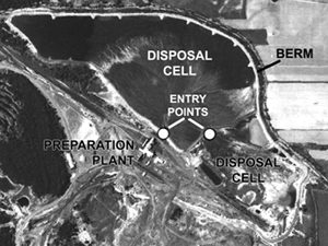
Figure 1. Photograph of the Minnehaha coal-slurry deposit (ID_IGS: D3) showing its bounding berm. The photograph was taken in 1954 (Photo ID: QO-1N-113) and has been altered to enhance contrast. The width of the area shown in the photograph is approximately 950 m.
In the early 1970s, color-infrared Earth Resources Technology Satellite (ERTS) imagery (scale, 1:120,000) taken in May 1971 was used to map CSDs, and the total acreage of such deposits in Indiana was estimated to be 1,631 acres (Wobber and others, 1974, 1975). In the late 1970s there were two significant reconnaissance investigations that involved the mapping of CSDs in Indiana. Weismiller and Mroczynski (1978) provided maps showing areas of CSDs, as well as areas of gob deposits (namely, coarse-grained refuse from coal preparation). Using color infrared aerial photographs taken in the early summer of 1971 and techniques of remote sensing, they mapped 242 polygons, of which 29 are designated as being CSDs. Personnel of the Indiana Department of Natural Resources, Division of Reclamation, subsequently made site visits to verify the interpretations. Eggert (1979) provided a map showing the point locations of 44 CSDs and active preparation plants. He described site conditions of the CSDs and provided tabulated information about each site, including mine names, active dates, coal beds mined, total production, and so on.
Slurry Emplacement
Fine-grained refuse in the form of slurry was removed from coal-preparation plants through pipelines. The point at which the slurry emerged from the pipe and entered a disposal cell is referred to alternatively as the "discharge point" of the pipe or the "entry point" of the disposal cell. At underground mines, disposal cells were specially constructed, but at many surface mines, preexisting features such as final-cut pits, inclined haul roads, and spoil deposits were utilized for slurry disposal.
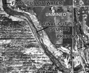
Figure 2. Photograph of the Airline coal-slurry deposit (ID_IGS: E3), where a final-cut pit was used for slurry disposal. The photograph was taken in 1949 (Photo ID: QP-3F-122). This coal-slurry deposit was studied by Eggert and others (1980). The width of the area shown in the photograph is approximately 1,000 m.
Disposal cells sometimes consisted of impoundments ("slurry ponds") that were bounded by berms constructed of gob or spoil (disturbed and displaced overburden from surface mining) (fig. 1).
A description of the construction of such a slurry pond at a mine in southern Illinois, where the slurry was subsequently re-mined and sold, is provided
in an article in Coal Age (1950a, p. 85):
The sludge pond is built up gradually over a period of years by continually building one levee on top of another. To start the pond [the slurry-plant
superintendent] first laid down an 8- to 10-ft levee of clay on three sides of a 1,000-ft square area. The levee on the fourth side of the square-the
south side-was built of gob. The discharge end of the slurry pipe was mounted at the northwest corner of the square and the slurry then was pumped in.
Water draining down through the slurry could not pass through the clay levees, but did seep through the gob levee, and finally into a make-up water
reservoir. From there the water was recirculated to the preparation plant.
When the slurry neared the top of the original four-sided levee, another levee was built on top. The new levee was made of gob on all four sides. Slurry
continued to enter the sludge pond, but the water seeping down through the slurry still could not escape through the bottom clay levee on three sides. It
did filter through the original gob levee, however, and continued, as before, to flow into the reservoir. Thus adding one levee on top of another, Peabody
has been able to build the sludge pond up to almost any desired depth. The pond now being mined is some 50 ft deep.
At some surface-mine operations, final-cut pits were used as disposal cells (fig. 2). Within active surface mines, coal is typically trucked out of active pits on haul roads. These haul roads, or the remnants of haul roads, were sometimes subsequently used for disposal of coal slurry after active mining had ceased.
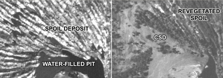
Figure 3. Photographs of the Chieftain coal-slurry deposit (ID_IGS: B9) in 1946 (left) and 1954 (right) showing the infilling of troughs within a spoil deposit with slurry. By 1954, the spoil ridges were already being revegetated with trees. The photographs (Photo IDs: GN-2D-008 and GN-1N-096) have been altered to enhance brightness and contrast. The width of the area shown in each photograph is approximately 400 m.
Spoil deposits were also utilized as disposal cells at some surface-mine operations. Slurry flowed through the troughs between steep-sided spoil ridges; as a trough became filled, the slurry would overflow through notches in the ridges into adjacent troughs (fig. 3). Water would percolate down through the spoil, leaving a dry surface that could later be reclaimed.
Internal Characteristics
From the 1970s through the middle 1980s, personnel of the Indiana Geological and Water Survey (IGWS) conducted a program of mapping, sampling, and analyzing deposits of gob and slurry. A total of 519 samples was collected from CSDs and analyzed by IGWS personnel (Miller and Eggert, 1982, p. 50). Some washability tests and grain-size analyses were performed in addition to chemical analyses, such as proximate and ultimate analyses. The samples were obtained from 93 different drill holes associated with 14 coal-waste areas. Using these data, Eggert and others (1980) provided a detailed characterization of coal slurry at the Airline-Sponsler Mine, while Eggert and others (1981) described CSDs associated with the Green Valley Mine. Based upon the entire sample set, Miller and Eggert (1982) estimated that the total tonnage of CSDs in Indiana at that time was about 40 to 50 million tons distributed across 1,400 acres, which they estimated to represent about 20 million tons of recoverable coal. Some additional samples were collected and analyzed in the middle 1980s.
Complex internal variations in the mineralogical, chemical, and textural characteristics of CSDs have been demonstrated to exist. At a CSD in southern Illinois
where slurry was mined and sold, the mine officials made the following observations (Coal Age, 1950a, p. 85):
In planning the sludge recovery, [the slurry-plant superintendent] and other Peabody officials figured this way: the high-ash slurry would settle out nearest the
discharge end of the sludge pipe and ash content would fall in proportion to the distance from the discharge. Thus ash content of the coal in any area of the sludge
pond could be predicted with reasonable accuracy. They also figured that the slurry farthest from the discharge would be the very smallest size and that, for that
reason, it could not be dried without added cost.
They were right on all counts. That's why the sludge pond is "mined" no closer than 100 ft or so to the discharge point and no closer than 200 ft or so to the…farthest
corner of the pond. "Mining" thus is confined to the center area of the pond, where ash content and moisture are marketable.
A more scientific approach was taken by Eggert and others (1980), who investigated a slurry deposit that had been emplaced in a long (3,000-m), narrow (80-m) final-cut pit at the Airline-Sponsler Mine, Greene County, Indiana. They described the sediments in the deposit as a "manmade prograding fan-delta system" in which there were vertical and lateral sequences of sediments whose physical characteristics were predictable (Eggert and others, 1980, p. 255) (fig. 4).
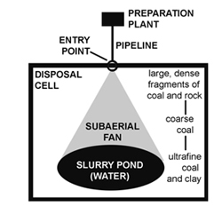
Figure 4. Schematic diagram illustrating the distribution of particle sizes in a disposal cell.
As the slurry emerged from its discharge pipe, its fluid velocity was suddenly reduced, resulting in the deposition of large pieces of coal, coal minerals, rock fragments, and sulfide-mineralized coal that were high in ash and sulfur and possessed low calorific value (Eggert and others, 1980, p. 259-260). As the slurry flowed across the subaerial portion of the deposit, the remaining coarse tailings were deposited. When the slurry reached the standing water of a pond, its fluid velocity dropped sharply and only clay and ultrafine coal remained in suspension, gradually settling to the bottom. Eggert and others (1980, p. 258) estimated that the particle sizes of about half the deposit were less than 140 mesh (0.0965--0.1067 mm) and noted that such small sizes absorb large amounts of moisture and cause significant material-handling problems.
The slurry deposit investigated by Eggert and others (1980) had a single entry point and a simple geometry. Physical characteristics of deposits are much less predictable where the geometries of the cells are more complex or where multiple entry points may have existed. As described in a later section of this report, development of the Chinook CSD was particularly complex. Initially, slurry was disposed of in a final-cut pit. When the pit was filled, an impoundment was build across the lower end of the pit and the slurry overflowed onto undisturbed ground on one side and into an area of spoil ridges on the other. The thickness of such a CSD, as well as its chemical and textural characteristics, can vary greatly across the deposit (fig. 5).
METHODS

Figure 5. Idealized cross section showing variations in thickness of a complex coal-slurry deposit (such as the Chinook coal-slurry deposit) that was emplaced above undisturbed ground, a final-cut pit, and a spoil deposit.
Feature Identification
For this investigation, the paper maps of Eggert (1979) and Weismiller and Mroczynski (1978) were digitized to provide a GIS layer showing the approximate locations
of CSDs and associated preparation plants in the late 1970s. Locations of additional preparation plants that operated after 1978 were obtained from various reports
published by the IGWS (Hasenmueller, 1981, 1983, 1986, 1991; Alano and Shaffer, 1994; Blunck and Carpenter, 1997; Eaton and Gerteisen, 2000), as well as from various
editions of the Keystone Coal Industry Manual (Coal Age, 1987, 1989, 1991, 1993, 1995, 2000, 2005).
Using the shapefile of approximate locations to identify areas of interest, about 160 historical aerial photographs taken in those areas between 1937 and 1980 were then obtained from the archives of the IGWS and georeferenced. Other imagery that was used included Digital Orthophoto Quarter Quads (DOQQs) of the U.S. Geological Survey from 1998, and imagery of the National Agricultural Imagery Program from 2003 and the Indiana Orthophotography Project from 2005.
On aerial photographs, preparation plants are recognizable as tall structures that may cast long shadows and are sometimes associated with silos, conveyor belts, or smoke stacks (fig. 6). Preparation plants, particularly older plants and plants associated with underground mines, are often situated on rail lines (with multiple tracks adjacent to the plants), while more recent plants associated with surface mines are often connected to various pits by broad haul roads that are distinctive on aerial photographs. However, the plants (particularly those associated with surface mines) were often dismantled or moved soon after mining activity shifted to other areas.
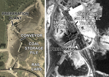
Figure 6. Examples of preparation plants on aerial photographs. Left: Photograph of the Old Ben No. 2 preparation plant (ID_IGS: J1) and associated features taken in 2003 as part of the National Agricultural Imagery Program. The photograph has been rotated so that north is to the right. The width of the area shown is about 300 m. Right: Photograph of the Tecumseh preparation plant (ID_IGS: K2) taken in 1953 (Photo ID: QV-2M-39). The width of the area shown in the photograph is about 325 m.
As part of this investigation, the identification of coal-slurry deposits on imagery involved the evaluation of several factors. CSDs are typically situated close to preparation plants, although in some locations slurry is pumped or flows for considerable distances through pipes or ditches before entering a disposal cell. Other factors indicating the existence of a CSD include the presence of berms, a generally dark gray or black appearance (except where the deposit is highly oxidized or where salts have formed on the surface), the existence of braided or meandering stream channels (indicating a flat-lying deposit), and an absence of shadows (indicating that the deposit has low relief).
Older, unreclaimed CSDs may exhibit erosional features that typically have relatively low relief, in contrast to coarse-grained gob deposits, which were created by dumping refuse in large piles (fig. 7). Unreclaimed gob deposits are also typically dark gray to black in color, but they may also exhibit steep-sided, eroded edges that cast long shadows. Gob deposits may also show evidence of straight travel ways on their upper surfaces where dump trucks traversed the deposit.
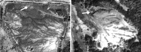
Figure 7. The appearance of a coal-slurry deposit (left) and a gob deposit (right) at the Friar Tuck Mine (ID_IGS: D4) on September 30, 1974. The width of the area shown on the photograph on the left is about 550 m; the width on the right is about 400 m. Neither photograph has been enhanced. The bright white area on the south end of the gob deposit is where the gob had been burned (probably as a result of spontaneous ignition), resulting in the formation of baked shale ("red dog"). The arrows indicate the locations of photographs taken on the ground and shown in Figure 8.
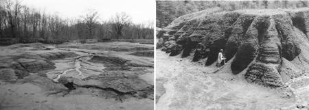
Figure 8. View of the eroded surface of the Friar Tuck coal-slurry deposit (ID_IGS: D4) (left) and an eroded gob deposit (right) at the same mine site. See Figure 7 for the locations of the photographs.
Although both CSDs and gob deposits are typically dark gray to black, the more elevated (and drier) portions of CSDs are often light-colored to white because of more pronounced weathering or the formation of salts on the surface (figs. 9 and 10).
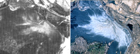
Figure 9. The most elevated and weathered portion of the Chinook coal-slurry deposit (ID_IGS: C1), as it appears on a black-and-white aerial photograph from 1976 (left) (Photo ID: 18021-173-76) and on a color photograph from 1996. The photograph on the left has been enhanced to increase brightness and contrast. The width of the area shown in each photograph is about 900 m.
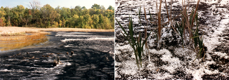
Figure 10. During hot, dry periods in summer, white salts precipitated on portions of the surface of the Friar Tuck coal-slurry deposit (ID_IGS: D4), prior to its reclamation. A detail of the surface is shown on the right.
MAPPING
Wherever possible, preparation plants were identified on historical aerial photographs or other imagery and their locations were digitized directly from the imagery using ESRI ArcMap to create a point shapefile showing exact locations (COAL_PREPARATION_PLANTS_IN.SHP). Sixty-nine preparation plants were so identified and mapped from photographs taken between 1937 and 2005. Eleven additional plants could not be identified on any available imagery, but their approximate locations were inferred from features on imagery, together with consideration of other documentary evidence. Because the names of some mines and associated preparation facilities change through time, a unique identification number (ID_IGS) was assigned to each facility. The identification number of the historical aerial photograph or other imagery from which each feature was digitized is provided in a database field named "ID_HAP." More information regarding the shapefile is provided in its metadata (COAL_PREPARATION_PLANTS_IN.HTML). Supplementary information regarding each preparation plant is provided in a Microsoft Excel spreadsheet (COAL_PREPARATION_PLANT_DATA.XLS). Fields and coded values that are used in the spreadsheet are defined in COAL_PREPARATION_PLANT_DATA.HTML.
Using historical aerial photographs and other imagery, features having characteristics similar to coal-slurry deposits, as well as selected features that were in proximity to preparation plants or to known CSDs, were identified and their boundaries digitized directly from the imagery to create an ESRI ArcMap polygon shapefile (COAL_SLURRY_DEPOSITS_IN.SHP). A selected subset of data extracted from the database file associated with this shapefile (COAL_SLURRY_DEPOSITS_IN.DBF) is provided in a Microsoft Excel spreadsheet (COAL_SLURRY_DEPOSITS_IN.XLS). The identification number of the historical aerial photograph or other imagery from which each feature was digitized is provided in an attribute field named "PHOTO." A total of 375 polygonal features were so mapped. A unique identification number (ID_IGS_PLY) was assigned to each feature.
Because historical aerial photographs are typically black and white and may be of poor resolution, and because CSDs are sometimes difficult to differentiate from gob deposits or other disturbed or barren areas associated with active mining, the recognition of CSDs required subjective interpretations by the investigator. Therefore, a qualitative indicator of the investigator's confidence in his interpretation was assigned to each feature in COAL_SLURRY_DEPOSITS_IN.SHP and COAL_SLURRY_DEPOSITS_IN.XLS in an attribute field named "GRADE." An explanation of these indicators is provided in the metadata for the shapefile (COAL_SLURRY_DEPOSITS_IN.HTML).
Subsequently, 97 features (representing 952 acres) that were initially considered to be possible CSDs were reevaluated, and, upon further consideration, it was decided that they probably do not contain slurry. Although these features were retained in COAL_SLURRY_DEPOSITS_IN.SHP, they are categorized as "NS" (namely, "not slurry") in an attribute field named "TYPE." Also, 80 water-f


